At SoloPoint Solutions, we strive to help our clients go from design to prototype as quickly as possible; which is why we invited Bill Schnoebelen, Founder of Circuit Case, to share his rapid prototyping expertise with us:
Many years ago, we started a process of selectively dimensioning drawings and using the model as documentation. This process works very well. I very rarely have any issues with parts out of spec. This technique works for machined, sheet metal in the flat, and plastic parts.
Background
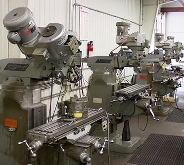
20 years ago it was very common for machinists to use manual Bridgeports. The machinist would consult the print for the required dimension, subtract or add for tool compensation, then spin the dials to get the tool to the cutting position in a manner which eliminated backlash. If the engineer missed a dimension, they were sure to get a phone call or tap on the shoulder if the shop was in-house.
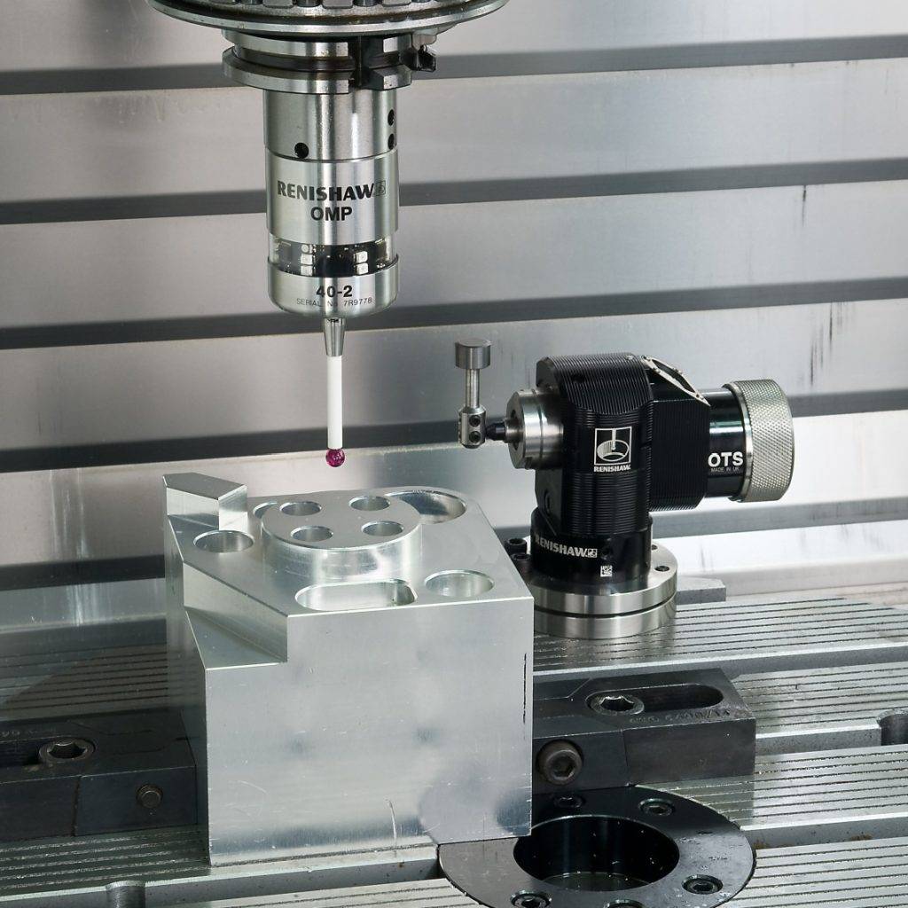
Nowadays, the information is transferred electronically. Electronic data is fed from CAD to CAM. The CAM allows the machinist to pick the features directly from the solid model. The CAM generates a tool path which is then translated into G-code for a particular machine. Toolsetters measure the tools while probes measure the part based on the origin chosen in the CAM. Based on the measurements the G-code moves the servos into position with on ball screws with zero backlash.
This makes for a much more controlled process. Errors come in the form of loading the wrong tool or not positioning the part correctly in multiple setups. Tolerances come from tool wear, tool deflection, and accumulated tool out of round. With these tolerances modern days machines will hit +/-.003” all day long. In general, design for +/-.005” and you will not have any issues.
Process
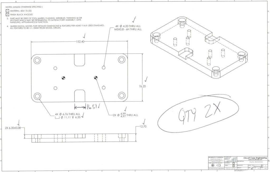
If you are going to use the model as your documentation, you still need to include certain information on the drawing. Here is a list:
- Material – The material does not come through with a step or parasolid file. It is best to include it on drawings.
- Finish – The finish as well does not come through in step or parasolid files. It is best to include it on drawings.
- P/N & Revision – If you want clear communication include these. Ignore them if you don’t mind fumbling handoffs.
- Tapped Holes – Including these on the drawing avoids guess work. Hint: use hole features in SolidWorks to make this faster.
- Any Tolerances greater than +/-0.127mm[.005″] – We have adapted to machine to ISO 2768M which is a bit tighter under 6mm[.236”]. Industry standard has been +/-0.127mm[.005″] so it is good practice to call out any tolerances greater than this. These include: Dowel Pins, Bearings/Bores, Keyed Pockets, etc.
- Stock/Overall – These overall dimension provide the machinist a way to verify the process at the machine. They also make quoting faster although this is moving towards automation.
A drawing give the machinist a way to check the part as well. They can add any other dimensions they require. They can check off dimension when they are verified at the machine.
Release Documentation Macro
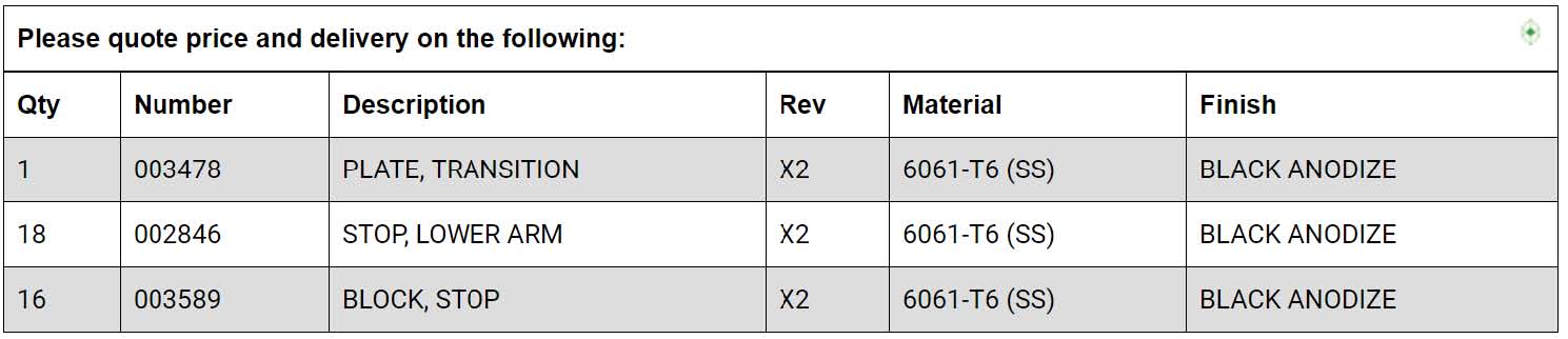
On final release of the parts, we use a macro simple called Release Documentation. This gives you a quick way to produce clear concise release packages with order list.
Release Documentation can be downloaded from here.
Conclusion
It is up to you decide if this process will work for your parts. Remember you need vendors who use electronic data for their CAM. I, however, find this more common than not. The specifications guiding this are ISO2768 and ASME Y14.41. ISO2768 seems to have more international adoption.
In order to stay competitive and adapt to market changes, development cycle needs to get shorter. We as engineers must rely on process to control the details. This is simply a better process.
It allows us to focus more on what is important, the design.
On January, Bill will be sharing with us more tips to get you from design to prototype faster and more efficiently. Stay tuned!