This is part 2 of our quick turn prototyping series with Bill Schnoebelen – president of Circuit Case Engineering:
I started my career designing automation equipment, with a machine shop in the next room. There were two things I quickly learned from this experience. The first is that designs that looked good on paper do not always work. You have to build it to prove it. The second is that to get parts quickly, you need to design within the machine shop’s capabilities.
When I started to do product design, these lessons were the same. The difference was you would multiply any problems by ordering larger quantities of parts. Everybody wants a prototype!
Today, I own a development shop. We do our own designs as well as make prototypes/one-offs for others. Whether built in-house or outsourced, our internal designs consistently flow smoooooothly. I would like to share with you some of the strategies we use for machined parts.
Design
Learn and design parts within standard manufacturing process. This leads to lower cost, fewer rejects, and faster design iterations. Below are some guidelines we use when designing for our in-house
milling:
As a general rule, when designing pockets, allow for a relief or keep the internal radii so that the endmill depth of cut is under 5X the endmill diameter. As shown in the example, for a 0.625” deep pocket the smallest endmill should be 0.625”/5= 0.125”. We then make the corner radii slightly bigger than the endmill radii to avoid chatter as the endmill transitions around the corner. There are exceptions to this rule and we have ways to accomplish them, but they add cost and time.
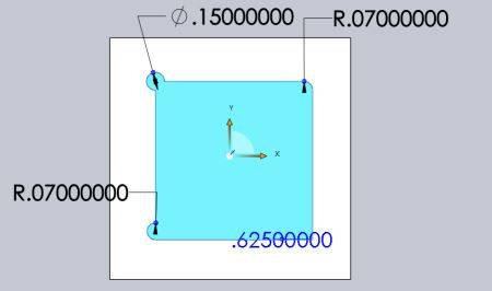
To remove the radius inside your pocket, add a corner relief. The 0.150” diameter and 0.07” side radius show two ways of achieving this.
Use standard taps and keep the depth to under 3X diameter. We design to 1X – 2X diameter. Whenever possible, use through-tapped holes. If you use a blind-tapped hole, then allow a minimum of 3X thread pitch clearance beyond the threads for the pilot drill. This will allow a place for stray chips to go without breaking the tap.
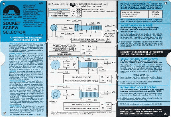
Spend a few bucks on a screw chart so you quick reference to fastener data.
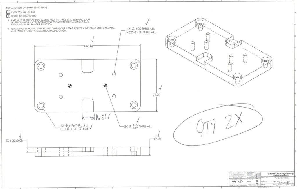
Unless there is a real need, avoid cluttering the drawing with every single dimension. We think of drawings as a way for the machinist to check the process for each setup. Most dimensions can be taken from the model in the CAM. We do give the overall size, highlight any tight tolerances, and make sure the tapped holes are called out as this is what is important! It is also very important to include a part number and revision!
Quoting
Every machine shop has a different way to quote. Our system extracts parametric data from the solid model and compare it against historical measured cycle times.
A good chunk of the cost for low volume parts is CAM and Setup. The graph’s below compare volumes of 2 pieces to 10 pieces. The red hue pie slices indicate setup costs. Note how this becomes much less significant as quantity goes up.

CAM
As mentioned, we use the CAD files to create the CAM. CAM is a significant cost for low volume. If you have several similar parts, the CAM can be automated or at least semi automated.
Setups
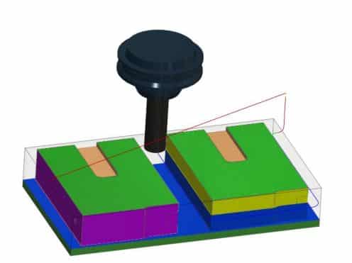
Custom setup tooling is also part of the NRE. As you can see in the above charts, setups are expensive for low-volume parts. We do everything from simple 6” vise with hard jaws to very intricate special setups. Below are examples of
some of our frequent setups:
- Serrated jaws to hold raw stock on OP1
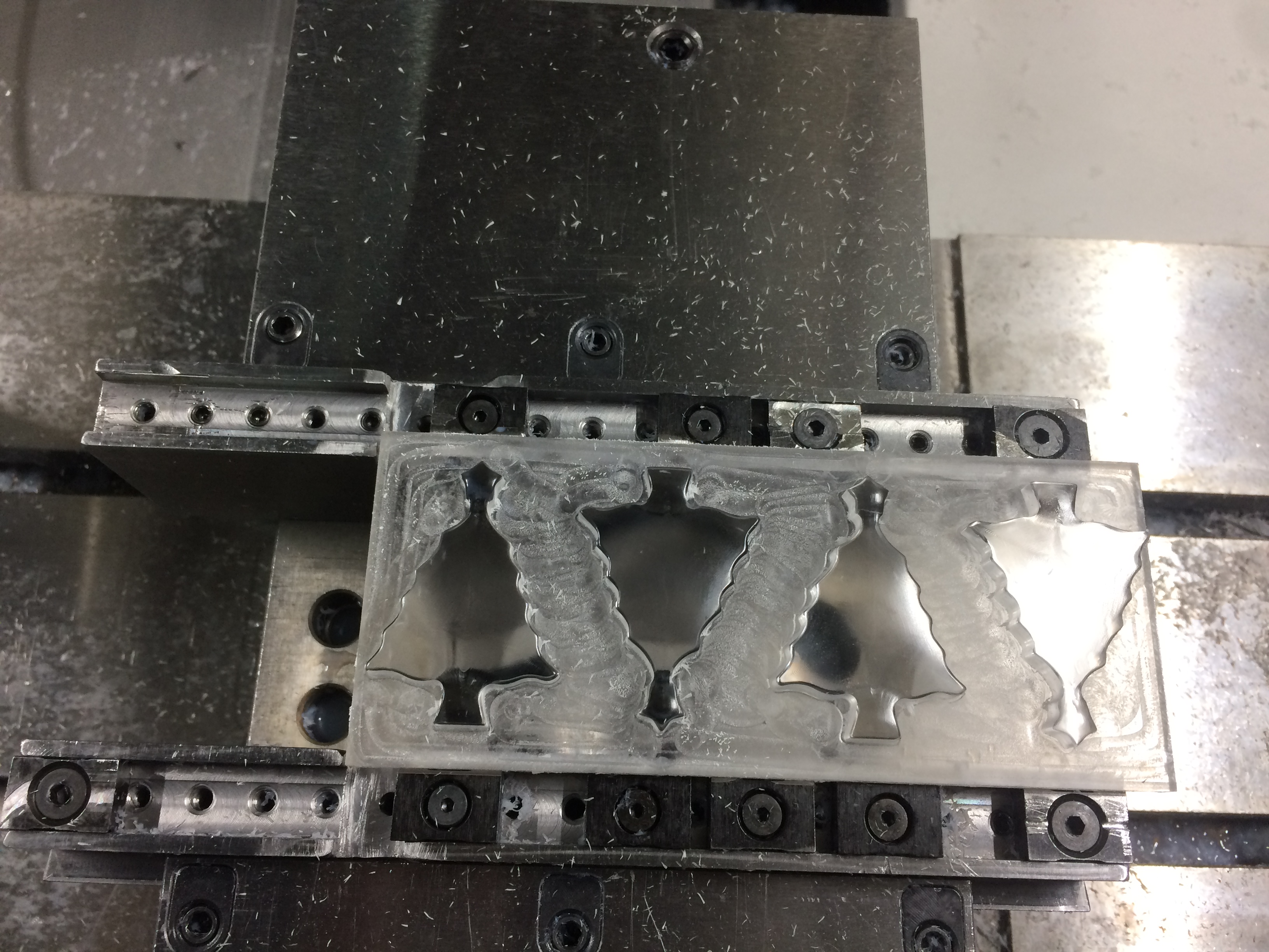
- Soft Jaws to hold parts on OP2
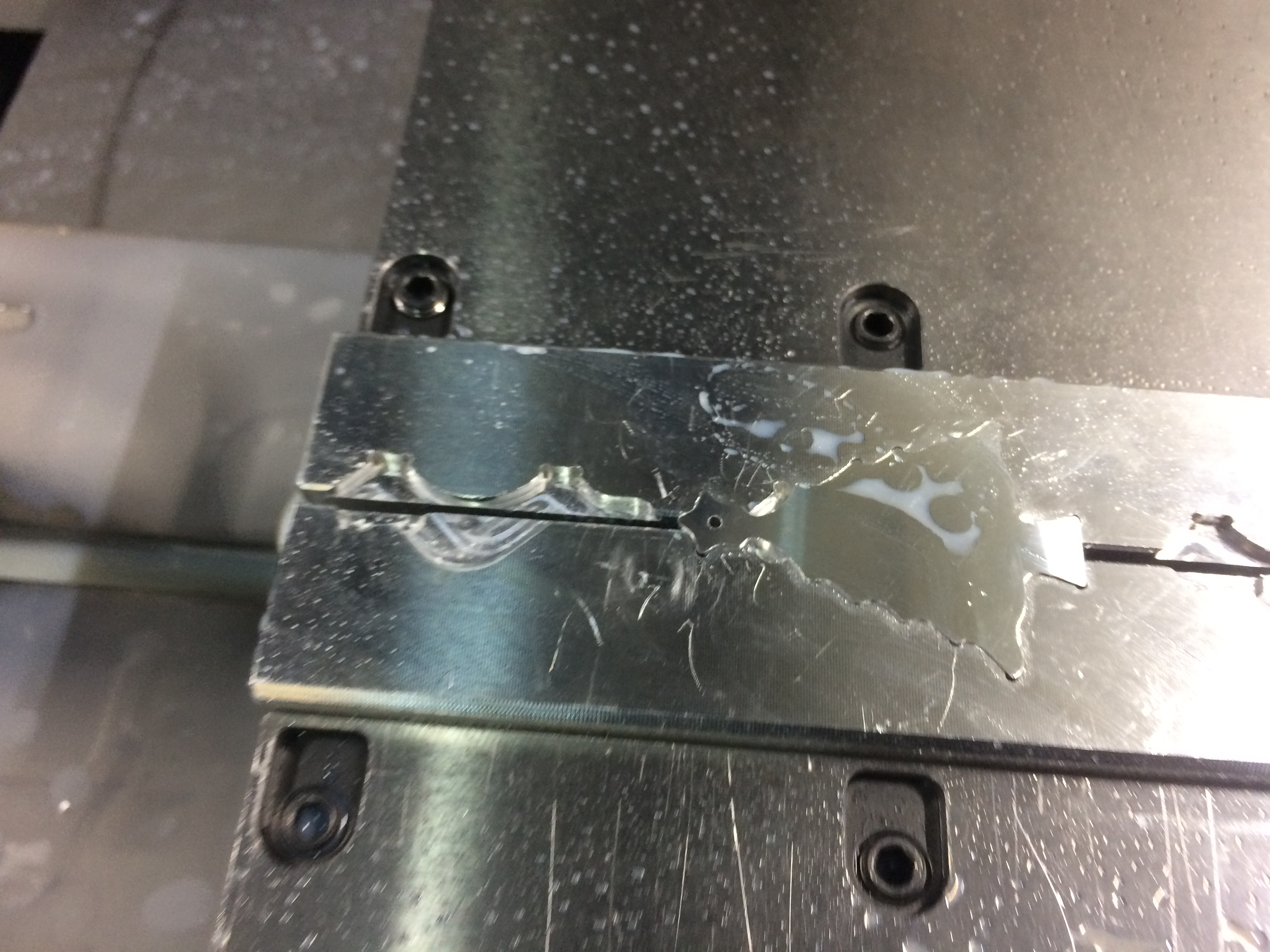
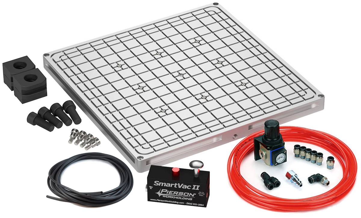
- Vacuum plate
Prototyping Strategies
During the development stage, it is important to have good direct communication with your development shop. From a development shop perspective, it is certainly a good idea to have direct communication with the engineer. There are always questions that need to be answered. Make sure you pick a shop(s) with good direct communication and with a process that fits your needs.
If a big job is coming up, a lot of time and money can be saved by planning. Rush orders of material or tools can easily more than triple the cost. You must plan ahead in order to have the material and machine time available.
If you have a large amount of similar parts, then you can set up quoting parameters up-front and create blanket purchase orders. This way, you can shave days off each part delivery! Additionally, similar parts can lead to automated or reuse of CAM. The setups for these parts will become standard and, therefore, require less time.
If you have a project that you can write specifications for and hand off, a design and build shop is a very good option. The combined engineer/machinist can reduce design iterations from days to hours. Cost savings are inherently built in because designs take the path of least resistance which meet the specification. Updating the CAD is ensured because it is driving the CAM.
The project specification is more suited for fixtures, industrial robots, and automation in small shops like ours. The emphasis is on cycle time and functionality vs aesthetics. Lately we have been taking advantage of today’s easy to use microprocessors and low cost PLCs on these projects. This greatly reduces the entry price and time to simple automation for testing and manufacturing.
Bill Schnoebelen has 20+ years experience in design engineering and prototyping. To learn more about his services, ask questions or for RFQs, click on the link below: